Extending Scanner Dynamic Range
One of the limitations in photographic recording media, be it film or digital capture is dynamic range. Most color transparency film has a dynamic range of roughly 5 stops between completely blocked up shadows to completely blown out highlights. Color negative film, extends this range to about 7 stops and black and white film to about 10 stops. This is a limitation that we as photographers have learned to live with.
With the advent of digital photography and the gradual replacement of the wet darkroom with the digital darkroom, new techniques have been developed to extend this dynamic range. Techniques involving the blending of two or more exposures of the same scene, one for shadow detail and the other for highlight detail, are available and can be found HERE as well as many other sites and in many books as well. All of these techniques discuss how to extend the dynamic range of the actual recording media. With digital capture, the problem ends there, in that the extension of the dynamic range is solely in the original capture.
However, for the film photographer, who then processes an image digitally, finds that the limiting factor in the dynamic range of the final image or print is not at times in the film but in the scanning hardware used to digitize the image. The Dmax number gives some indication of a scanners dynamic range. This number is computationally determined from the following equation. Dmax = log 2^x where x indicates the scanning bit depth of the scanner. For example, an 8-bit scanner can scan an image and produce 2^8, or 256 levels, and has a Dmax of 2.4. A scanner capable of scanning at higher bit depths, such as 12, 14 or 16 will be capable of producing images containing levels of 4096, 16384, or 65536 respectively, and have corresponding Dmax values of 3.6, 4.2, or 4.8. The Dmax number and what claims come with it regarding the dynamic range of the scanner is however theoretical and many other factors contribute to the final dynamic range of the digital image.
I have had my film scanned on many different scanners, from flatbed scanners to drum scanners. In all cases, with images containing a large dynamic range, the scanned image has come up short of reproducing what is on the transparency. I have tried the multitude of blending techniques of combining multiple film exposures and have found it much more work than it was worth, due to the problem of registering the two or more resulting digital images that were scanned separately. When the final image is a 16 x 20 print, even the smallest error in digital registering will be garishly apparent.
I currently own two scanners of reputable quality, the Nikon LS4000 for 35mm film, and the Microtek Artixscan 1800f flatbed for large format film. The Nikon scanner can scan and deliver a 14-bit image and claims a Dmax of 4.2. The Microtek can scan and deliver a true 16-bit image with a claimed Dmax of 4.8. Yet, despite the claims of the large dynamic range that is possible, both scanners do a poor job of getting into the dark shadows to extract evident detail seen in the transparency under a loupe. Both scanners however, have adjustable exposure controls and I started experimenting with blending multiple exposures, not from my camera but from my scanner. The procedure I follow is described below.
1. Scanning
1.a Base Scan
Begin by scanning the transparency at a normal exposure level. This would retain good highlight detail throughout the image, but most often than not, the shadows would be blocked up. Name this image the Base image.
1.b Shadow Scan
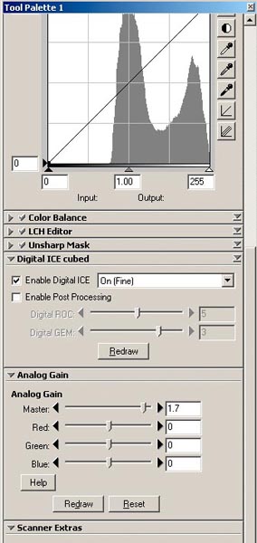
Then without moving the transparency, scan it a second time at an increased exposure level. With the Nikon scanner, using NikonScan software increase the exposure level by increasing the master analog gain by 1.5 to 2 stops over normal. If that is not enough then gingerly, start pushing the R, G, and B channels up by equal amounts as well until the shadow detail is sufficient.
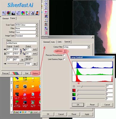
With the Microtek scanner using Lasersofts SilverFast Ai, the lamp control is accessible from the main tools menu via the Options button. On the options menu is a Lightness button that opens a window containing sliders to control the lamp brightness. The lamp brightness and RGB channels range from 0 to 510, increasing the lamp brightness or channel values is equivalent to increasing the exposure. Make several scans with varying increased lamp brightness until adequate shadow detail is seen. This second scan will look terrible and all highlight detail is completely blown out, but that is not the detail of interest. Name this second image as the Shadow image.
2. Digital Blending
2.a Open both images
Then open both images using Photoshop or any other image editing software that can make use of layers. Since both images are from the same transparency scanned twice without moving the transparency in the scanner, the two images will register exactly.
2.b Combining both scans
Start with the Shadow image, by selecting the entire image, on the PC, and then copying it, . Next, select the Base image as the active image and simply paste the Shadow image onto the Base image, . Photoshop automatically sets the Shadow image as a new Layer on top of the Base image.
2.c Mask creation
At his point, what you will see on screen is the Shadow image as it is the top layer. A mask will be needed that will block out the blown out highlights and allow the shadow details to come through. Begin by examining each of the channels of the Shadow image layer for the channel that has the least highlight detail and select it , copy it and then create a new alpha channel and paste that copied channel into it, .
2.d Mask adjustments
Next, make levels adjustments to the alpha channel alone by moving the dark slider to the right and the white slider to the left to reduce the dynamic range of this black and white image to the point where the areas of the desired shadow detail are sufficiently black. Then invert the alpha channel image.
2.e Blurring the mask
Next, apply some Gaussian blur, perhaps 3 to 5 pixels to the inverted image in the Alpha channel. The Gaussian blur is an important step in this process. While making the Shadow image scan, the edges between the highlights and shadows tend to shrink in towards the shadows. When the alpha channel is inverted, the edges will also be inverted, extending the shadow regions in to the retained highlight regions and a strange offset halo will occur when the two scans are blended. The application of Gaussian blur to the inverted image in the Alpha channel will effectively reduce the infringement into the desired retained highlights by creating a pseudo-gradient along the edges of the mask.
2.f Applying the mask
Activate the Shadow image layer and add to it a layer mask. Then return to the channels panel and select and copy the Alpha channel, and . Return to the Shadow image layer and on the white layer mask. This will display a white image on screen. Next paste the copied alpha channel into the layer mask, . Then display the actual image again by using on the layer mask. What you will see now is an image that retains the highlights from the Base image and the shadows from the Shadow image. The strength of the Shadow layer can then be adjusted using the Opacity slider for that layer.
3. Additional Adjustments
Additional adjustment layers can now be added to the entire image as needed. To make adjustments to the highlights or shadows separately simply apply the alpha channel mask to the adjustment layer in the manner explained in step 2.f. For shadow adjustments use the alpha channel image mask as is and for the highlight adjustments paste the alpha channel in to the adjustment layer mask and invert it.
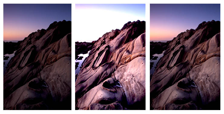
With this technique you can, for example, go from the image on the left shown below, with the shadows completely blocked up and adding the image in the center showing shadow detail, with some additional layer adjustments to obtain the image on the right. The adjusted image has excellent shadow and highlight detail retained as they were on the original transparency, effectively extending the dynamic range of your scanner.
|
|
|


